
In the actual execution of virtual production (VP) and augmented reality (AR), the most common underlying technical glitches encountered by technical teams are often not the rendering fidelity of the image, but ratherthe micro-jitter and slippage of visual perspective。
When the camera is stationary or performing an extremely slow push-in, the virtual background or AR elements on the large screen suddenly exhibit an extremely subtle “micro-tremor” that is imperceptible to the naked eye but instinctively sensed by the brain; or, when the camera pans quickly and stops abruptly, the virtual background produces a slight “bounce” or “drift” on the screen.
As the on-site System Integration Director (EIC) or tracking calibration engineer, you know well that this is not a rendering issue with the engine, but rathera high-frequency battle between mechanical vibrations in the physical world, thermal noise from sensors, and sampling delays in the digital world。
Whether using optical infrared tracking (e.g., Vicon, OptiTrack), inertial gyroscope tracking, or mechanical jib encoders, the raw 6DOF (six degrees of freedom) spatial coordinate data transmitted back to the system is essentiallyHigh-frequency Noise和Temporal Latencycontaminated data.
If this data is directly fed into LiveLink to drive a virtual camera in the native Unreal Engine (UE5), its built-in linear interpolation (Lerp) or simple exponential moving average (EMA) algorithm will immediately expose fatal industrial limitations: it cannot find a physical balance between“filtering noise (smoothness)”与“reducing latency (responsiveness)”With heavy filtering, the image lags and drifts; with light filtering, the background trembles at high frequencies.
Aximmetry By integrating industrial-grade mathematical filtering algorithms and a dynamic latency lock matrix in the underlying I/O link, it builds an indestructible mathematical firewall between chaotic physical motion signals and the absolutely rigid 3D rendering clock.
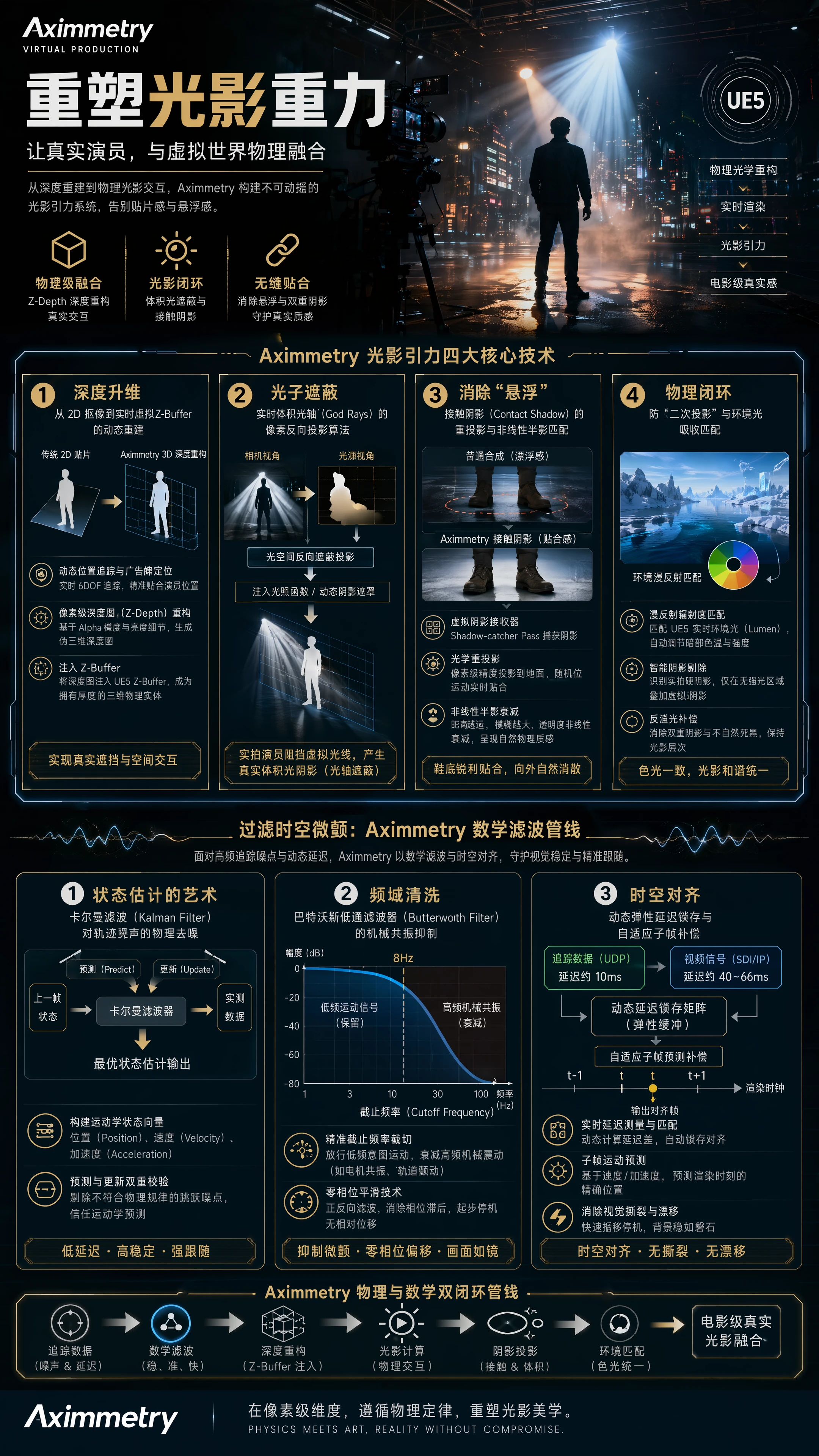
I. The Art of State Estimation: Kalman Filter for Physical Denoising of Trajectory Noise
Optical tracking systems can produce instantaneous coordinate jumps when encountering occlusion, reflections, or minor marker displacements; while inertial sensors, when stationary, output continuously fluctuating coordinates due to temperature drift and high-frequency thermal noise.
Traditional interpolation algorithms are “hindsight” methods—they only smooth based on erroneous coordinates that have already occurred, inevitably introducing significant lag.
Aximmetry's solution is to deploy aKalman Filter state estimatorat the data entry point. Its core logic is not simply to smooth the data, but touse a physical kinematics model to “predict” the true trajectory of the camera.
Constructing a Kinematic State Vector
Aximmetry's algorithm treats the camera as a physical entity with mass, inertia, and friction. It maintains a real-time state vector in memory that includes position, velocity, and acceleration.
Dual Verification of Prediction and Update
In each rendering cycle, the Kalman filter performs two steps:
- Prediction Phase (Predict): Based on the velocity and acceleration from the previous frame, the filter calculates the physical position where the camera “should” be in the current frame.
- Update Phase (Update): When the tracking network card delivers the latest measured coordinates, the filter evaluates this measurement. If the measured value suddenly undergoes an “instantaneous jump” that violates the laws of physical acceleration (e.g., a coordinate jump due to optical occlusion), the filter identifies it as high-frequency measurement noise, significantly reduces the weight of this data, and instead trusts the predicted value from the kinematic model.
Through this dynamic interplay between prediction and measurement, Aximmetry can perfectly filter out high-frequency glitches caused by sensor jitter or physical vibration with extremely low latency, keeping the background of a static camera rock-solid while preserving highly responsive motion feedback.
II. Frequency Domain Cleaning: Butterworth Low-Pass Filter for Mechanical Resonance Suppression
During jib/crane or handheld dolly shots, weak motor resonance, physical gaps in the rails, or even air vibrations from heavy bass speakers on set can be transmitted through the mechanical structure to the camera sensor, producing mechanical micro-resonances in the 10Hz to 30Hz range.
This specific frequency of micro-tremor is infinitely amplified in the 3D rendered image.
Aximmetry incorporates aSecond-Order Butterworth Low-Pass Filterwithin its flow graph, specifically designed to eliminate mechanical resonances in particular frequency bands:
Precise Cutoff Frequency Trimming
On-site engineers can set an extremely precise cutoff frequency (e.g., 8Hz) in Aximmetry based on the physical characteristics of the current equipment. The filter passes all motion signals below 8Hz—since the human intent to pan the camera and the smooth swing of a jib are low-frequency signals—while all mechanical resonances and vibration noise above 8Hz are ruthlessly and exponentially attenuated by its amplitude-frequency characteristic curve.
Zero-Phase Filtering
Ordinary low-pass filters cause the waveform to shift backward on the time axis (introducing phase lag) when filtering out high-frequency signals. Aximmetry enables advanced zero-phase smoothing in non-real-time recordings or live pipelines with a delay buffer. It filters the data stream both forward and backward, ensuring that the filtered motion waveform perfectly aligns with the original motion curve on the time axis. This completely eliminates jitter while ensuring that, during camera start-up and stop, there is no millisecond-level relative displacement between the background and the live footage.
III. Spatiotemporal Alignment: Dynamic Elastic Latency Lock and Adaptive Subframe Compensation
After addressing spatial coordinate noise, the system must face the ultimate challenge on the timeline—Temporal Latency Drift。
In complex all-IP (SMPTE ST 2110) or traditional SDI broadcast environments, the video signal from the camera sensor, after SDI encoding, optical transmission, and capture card decoding, typically incurs a physical delay of 2 to 4 frames (approximately 33ms to 66ms) before reaching Aximmetry. Meanwhile, tracking data sent via network cable (UDP) usually has a delay of only about 10ms.
This creates an asymmetric time difference of roughly 40ms. If composited directly, when the lens pans quickly to the left, AR elements, receiving the tracking signal earlier, will move to the right first, causing severe “visual tearing.”

 简体中文
简体中文  English