
In traditional film and television shooting and multi-channel live television broadcasting, multi-camera collaborative operation is a core means of ensuring the narrative rhythm of shots and saving shooting costs. However, in LED screen-based in-camera VFX virtual production, the image displayed on the LED screen must maintain strict perspective binding with the optical center of a single camera, which is the so-called in-frustum perspective. When two or more cameras are introduced on set, due to differences in physical viewpoints and viewing angles, the screen cannot simultaneously present the correct single-eye-point perspective for multiple physical cameras. This physical contradiction had long confined virtual production to the inefficient mode of single-camera single-take shooting.
With breakthroughs in LED master control clock technology, ultra-high frame rate panels, and GPU parallel multi-viewport rendering architectures, multi-camera virtual production has moved from laboratory prototypes to commercial feature films and broadcast-grade live applications. This article comprehensively breaks down the core underlying logic of multi-camera virtual production, mainstream engineering approaches, time-division multiplexing configuration essentials, and on-set director integration standards, helping teams build a highly industrialized multi-camera real-time shooting pipeline.
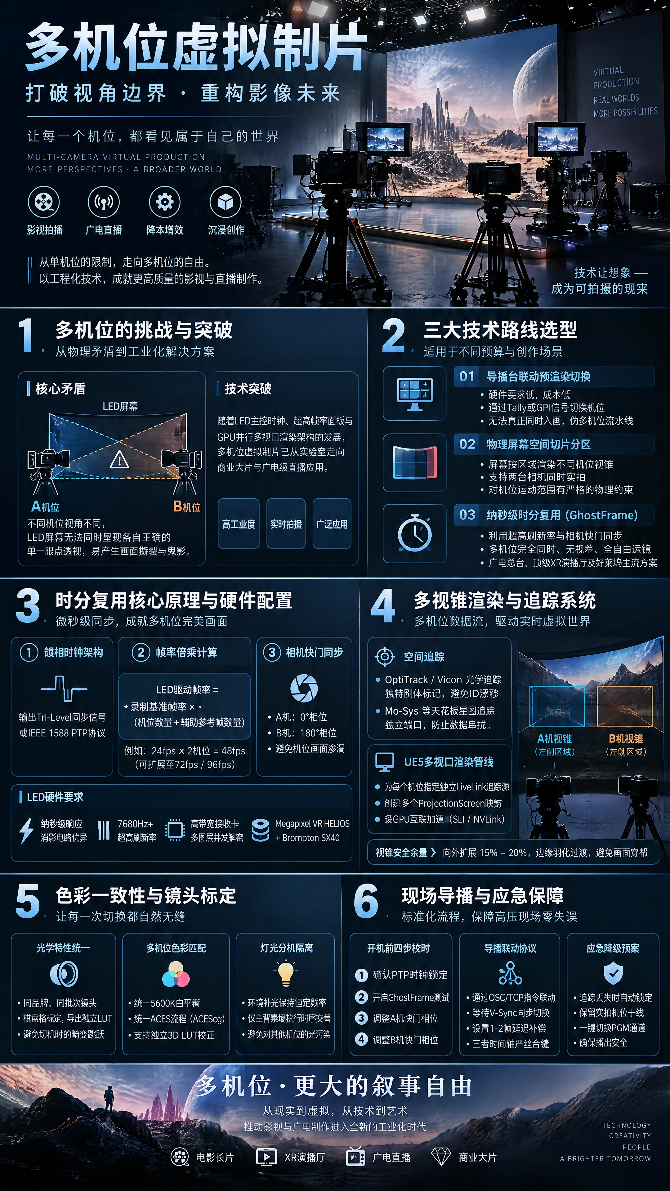
I. The Nature of Multi-Camera Frustum Conflicts and Selection of Three Major Technical Approaches
In LED virtual production, the inner frustum image captured by the camera is a pixel matrix that Unreal Engine real-time inverse-projects onto the screen's polygon mesh based on tracking coordinates. The core obstacle to multi-camera collaborative operation lies in the fact that cameras at different spatial positions produce line-of-sight projections in completely different directions. If two sets of images are rendered directly on the same screen, the overlapping physical field-of-view areas will produce severe image tearing and ghosting.
The industry has evolved three main technical approaches to overcome the multi-camera challenge, each suited to different production budgets and creative scenarios:
- Director Console-Linked Pre-Rendered Switching Approach This solution physically has only one primary rendered inner frustum. Two or more cameras, A and B, are deployed in the studio, with all camera positions equipped with high-precision spatial tracking kits. The system broadcasts the director's cut commands instantaneously to the render cluster via high-speed LAN through the Tally signal or GPI trigger pulse from the director's switcher.
At the instant the director presses the cut button, the UE5 rendering pipeline redirects the inner frustum's camera tracking data source from the A camera pointer to the B camera pointer during the next vertical blanking interval, while coordinating with the director's console to set a 1-to-2-frame black frame transition or micro hard cut. Its core advantage is that it imposes no special high-end requirements on the LED screen master control and receiving cards—a standard 60Hz or 120Hz system can run it, and hardware costs are extremely low; the disadvantage is that it cannot achieve true simultaneous on-screen presence and split-framing of two cameras, functioning only as a pseudo-multi-camera pipeline.
- Physical Screen Space Slicing and Zoning Approach In large circular studios or U-shaped long-arc studios, when Camera A is responsible for close-up shots on the left side of the stage and Camera B is responsible for wide shots on the right side, the inner frustums of the two cameras project onto non-overlapping physical areas on the LED wall.
In this case, the render cluster can divide independent Display Cluster viewports within UE5, mapping Camera A's frustum to the left LED cabinet group and Camera B's frustum to the right cabinet group, with the central common area filled with a generic outer frustum environmental background. This approach supports simultaneous live shooting with two cameras, but imposes strict mechanical and physical constraints on camera movement radius. Once a camera undergoes significant crane lateral movement causing inner frustum edge overlap, the background image at the junction will misalign and break the illusion.
- Nanosecond-Level Time-Division Multiplexing (GhostFrame) Clock Approach This is the thorough solution adopted by broadcast headquarters, top-tier XR studios, and mainstream Hollywood productions. It leverages the ultra-high refresh rate of LED panels (such as 240Hz or even higher) and the precise shutter synchronization technology of cinema-grade cameras to alternately flash background images for different camera positions at microsecond-level precision in the time dimension.
For example, the system drives the LED screen at a 120Hz total baseline refresh rate, with odd frames displaying Camera A's perspective image and even frames displaying Camera B's perspective image. By locking Camera A's sensor shutter open phase to odd frames and Camera B's shutter phase to even frames, the result is: to the naked eye on set, two superimposed ghost images are visible, but Camera A's monitor records a clean A-perspective world, and Camera B records a clean B-perspective world—both cameras shooting completely simultaneously, without parallax, with fully free camera movement.
II. GhostFrame Time-Division Multiplexing Underlying Engineering Principles and Hardware Configuration Chain
Time-division multiplexing technology is not simple software frame-splitting; it is an ultra-precision collaborative engineering system spanning master clock generators, LED video processors, high-speed receiving cards, and digital cinema camera shutter drivers.
- Phase-Locked Clock Architecture and Frame Rate Multiplication Calculation The prerequisite for implementing time-division multiplexing is that the broadcast-grade master generator must output high-precision Tri-Level sync signals or comply with the IEEE 1588 PTP precision time protocol.
Assuming the final broadcast or recording format is 24fps cinematic frame rate, in two-camera time-division multiplexing mode, the LED video processor's primary operating frame rate must be strictly increased to an integer multiple of the number of camera positions. At this point, the LED wall's display frame rate needs to be raised to 48fps, or even to 72fps or 96fps when inserting green screen keying frames (Hidden Green Screen).
The system calculation formula is: LED drive frame rate = recording baseline frame rate multiplied by (number of camera positions plus number of auxiliary reference frames)
- Camera Genlock Shutter Phase Microsecond-Level Offset Calibration All participating cameras must have a Genlock In interface, and the camera's internal sensor shutter system must support fine-grained sub-frame phase offset settings (Sub-Frame Phase Offset).
Taking a 48fps total frame rate (single frame period of approximately 20.833 milliseconds) as an example, Camera A is set to zero-phase start with a shutter angle of 180 degrees (exposure time of approximately 10.4 milliseconds); Camera B is also connected to the same sync signal but must set a shutter phase delay of exactly 180 degrees on the camera body (i.e., opening the shutter after a physical time delay of 10.416 milliseconds).
Through strict shutter phase difference, Camera A only absorbs photon energy from the A image during odd exposure windows, and the sensor is in the reset/readout period during even exposure windows, perfectly avoiding the B image; vice versa for Camera B. Any millisecond-level clock jitter will cause cross-talk leakage between camera images, producing semi-transparent ghosting in dark areas of the image.
- LED Hardware Panel Electrical Performance Requirements Conventional low-end LED cabinets cannot run GhostFrame technology. Multi-camera time-division multiplexing imposes three insurmountable physical specifications on LED cabinets: First, the constant-current driver chip must support nanosecond-level response with excellent ghosting elimination circuit performance, avoiding line trailing during odd-even frame switching. Second, the refresh rate must reach 7680Hz or above to ensure the camera captures full grayscale within extremely short exposure time windows, without horizontal scanning roll bars and color shift. Third, the receiving card bandwidth must support high-frame-rate multi-layer concurrent decoding; currently, mature industry solutions typically rely on Megapixel VR HELIOS processors combined with Brompton SX40 advanced firmware features.
III. Multi-Camera Tracking Data Flow and GPU Multi-Frustum Rendering Pipeline Design
To concurrently track multiple cameras in the same physical space and accurately feed data into Unreal Engine, deep restructuring of network topology and rendering architecture is necessary.
- Spatial Tracking System Bandwidth and Multi-Rigid-Body Isolation In multi-camera scenarios, spatial positioning systems face serious signal crosstalk risks. When using optical infrared reflective marker tracking (such as OptiTrack or Vicon), the rigid body kit mounted on each camera must have a unique geometrically asymmetric point layout to ensure the motion capture solver does not experience camera ID drift at any occlusion angle. If using encoded markers or ceiling star-map tracking (such as Mo-Sys StarTracker), the downstream data from Camera A and Camera B tracking sensors must be bound to different independent Ethernet ports or UDP ports to prevent high-frequency data packets from experiencing queue blocking within the network switch.
- Unreal Engine Multi-nDisplay Viewport Configuration In UE5's nDisplay configuration file, a single camera typically only needs to declare one root camera projection node. In multi-camera projects, multiple perspective viewports must be instantiated according to the number of camera positions, and mapping rules specified in the Cluster architecture: Step one, assign independent LiveLink tracking sources for Camera A and Camera B respectively, defining their respective sensor position compensation and FIZ lens distortion solving channels. Step two, create multiple ProjectionScreen mappings in the projection policy, binding Camera A's frustum and Camera B's frustum to corresponding render output buffers. Step three, in dual-camera time-division multiplexing mode, enable multi-GPU interconnect acceleration (SLI or NVLink), with Node 1 responsible for rendering Camera A's frustum view and Node 2 responsible for rendering Camera B's frustum view, finally aggregating through SDI or high-speed fiber DP cables into the LED processor's advanced layer mixer for clock interleaving.
- Multi-Frustum Edge Feathering and Inner Frustum Size Safety Margin Since cameras may produce slight physical tracking latency during aggressive crane movements or zooming, if the inner frustum is rendered tightly against the camera's field-of-view edge, it is highly prone to revealing edge cracks where the outer frustum has not rendered high precision during rapid whip pans. Engineering standards require: each inner frustum in multi-camera setups must be uniformly expanded outward by 15% to 20% safety margin (Over-render Margin) beyond the physical field of view, while enabling distance-based edge feathering on the outer ring of the frustum, ensuring that even if two frustums slightly overlap at the field-of-view edges, the transition band lighting remains smooth and natural.
IV. Inter-Camera Color Consistency, Lens Distortion, and Lighting Balance Calibration
In multi-camera shooting, what most easily breaks the illusion during post-production or director cuts is often not the background content, but the subtle differences between two cameras in color reproduction, depth-of-field transition, and distortion curvature.
- Cross-Body and Cross-Lens Optical Characteristic Unification Virtual production strongly discourages mixing cinema lenses of different brands and different coatings. Multi-camera work must use prime or zoom lens sets of the same brand and same batch. Before shooting, independent Brown-Conrady lens distortion calibration must be performed for each camera body and lens combination using a standard checkerboard calibration target, exporting distortion coefficients as independent LUTs and attaching them to corresponding viewports in UE5. Otherwise, during camera cuts, the straight edges of background objects will exhibit visible bending and jumping between the two camera positions.
- Multi-Camera Color 3D Matching Workflow First, environmental white balance baseline lock. All shooting cameras must have any auto white balance function disabled; the on-set LED wall outputs a pure white reference field, and a lux/color temperature meter is used to determine the color temperature (e.g., fixed at 5600K), locking all cameras to this physical value. Second, multi-camera ACES pipeline alignment. All camera signals output Log color space via SDI, uniformly entering their respective camera model's Input Transform modules (IDT) before the on-set monitoring matrix, all normalized and mapped to the ACEScg color space. Third, multi-channel independent color correction. High-end LED processors support loading independent 3D LUTs for different temporal frames of GhostFrame. This means targeted color fine-tuning can be applied to Camera A's image through the hardware processor without affecting Camera B's background presentation, achieving high-precision correction of background color under different sensor characteristics.
- Real Foreground Light and Virtual Frustum Dynamic Linkage Per-Camera Isolation In advanced virtual studios, DMX stage lighting is often pixel-level mapped with virtual scene lighting (Image-Based Lighting). In single-camera setups, ceiling and side LED screens serve dual purposes of fill lighting; but in multi-camera time-division multiplexing, if the auxiliary fill screen's brightness flickers with Camera A's perspective, it may cause light pollution on Camera B's foreground. The mature solution is to strip the environmental fill lighting canopy from the time-division multiplexing layers, maintaining constant-frequency global illumination, and executing frustum temporal alternation only on the primary background wall, ensuring that the physical shadow placement on actors does not flicker with camera cuts.
V. On-Set Director and Automated Switching Engineering Implementation Standards (SOP)
The high-pressure environment of multi-camera virtual production does not permit any operational errors; establishing standardized joint debugging and director coordination procedures is the baseline for ensuring industrialized output.
- Pre-Shoot Clock Phase Alignment Four-Step Method Step one, check and confirm the PTP master clock generator is in locked status with jitter error less than 1 microsecond. Step two, enable the LED processor's GhostFrame test mode, where the screen alternately outputs full-black and full-white high-contrast flickering images on odd and even frames. Step three, observe Camera A's monitor and fine-tune Camera A's shutter phase offset until Camera A's monitoring image reaches a completely stable pure white field with peak brightness and no black stripe leakage. Step four, observe Camera B's monitor and adjust Camera B's shutter phase until Camera B's monitoring image also reaches a completely pure white field. At this point, disconnect the test mode, restore the UE rendered image, and clock phase calibration is complete.
- Director Console and Unreal Engine Signal Bridging Protocol In studios without time-division multiplexing conditions using pre-rendered switching solutions, director switching must achieve automated low-latency linkage: Using Blackmagic Design or Sony director switchers, sending OSC (Open Sound Control) or TCP commands to the render workstation via Ethernet. UE5 runs a persistent background listening service; upon receiving a camera switch command, the system does not immediately cut the current image but waits for the next vertical sync signal (V-Sync) to synchronously update the camera matrix pointer. The director console sets a cut delay compensation (Cut Delay), typically set to 1 to 2 full frame times, so that the director console's physical button trigger, the engine's inner frustum calculation, and the LED panel pixel update are perfectly aligned on the timeline, completely eliminating instantaneous frustum tearing during camera cuts.
- On-Site Emergency Safety Degradation Protocol In critical live broadcast events, a multi-camera emergency degradation mechanism must be configured: If a camera's tracking sensor suddenly loses markers or data drifts, the master control system must, within 0.5 seconds, force-lock that camera to a fixed preset position via hotkey, or temporarily disable its inner frustum, reverting to global wide-shot mode. The main director switching matrix must reserve a pure hardware pass-through live camera feed line and a clean PGM downstream channel, bypassing virtual compositing nodes. Once the multi-camera rendering engine experiences a blue screen or stuttering due to VRAM overflow, the switcher can cut to the on-set wide-shot live camera or filler signal within a single frame, ensuring broadcast safety.
VI. Multi-Camera Virtual Production Technology Evolution and Future Landscape
Multi-camera virtual production is fundamentally restructuring the production relationships of the film and broadcast industries. With the maturation of next-generation Micro-LED technology supporting ultra-fast nanosecond-level time-division driving, and the deep optimization of UE5's multi-viewport rendering architecture for multi-GPU distributed cluster support, virtual studios are evolving from the current普遍 two-camera limit toward three-camera, four-camera, and even free multi-camera panoramic production.
For technical teams, mastering spatial geometric tracking, multi-clock domain phase locking, nanosecond-level shutter synchronization, and cross-color-space engineering control capabilities is the core watershed dividing traditional single-camera green screen production from modern industrialized virtual production powerhouses. Establishing rigorous cross-hardware calibration standards and full-link disaster recovery systems is what allows complex multi-camera virtual technology to unleash maximum narrative freedom and commercial value in feature film and top-tier live broadcast applications.

 简体中文
 English