
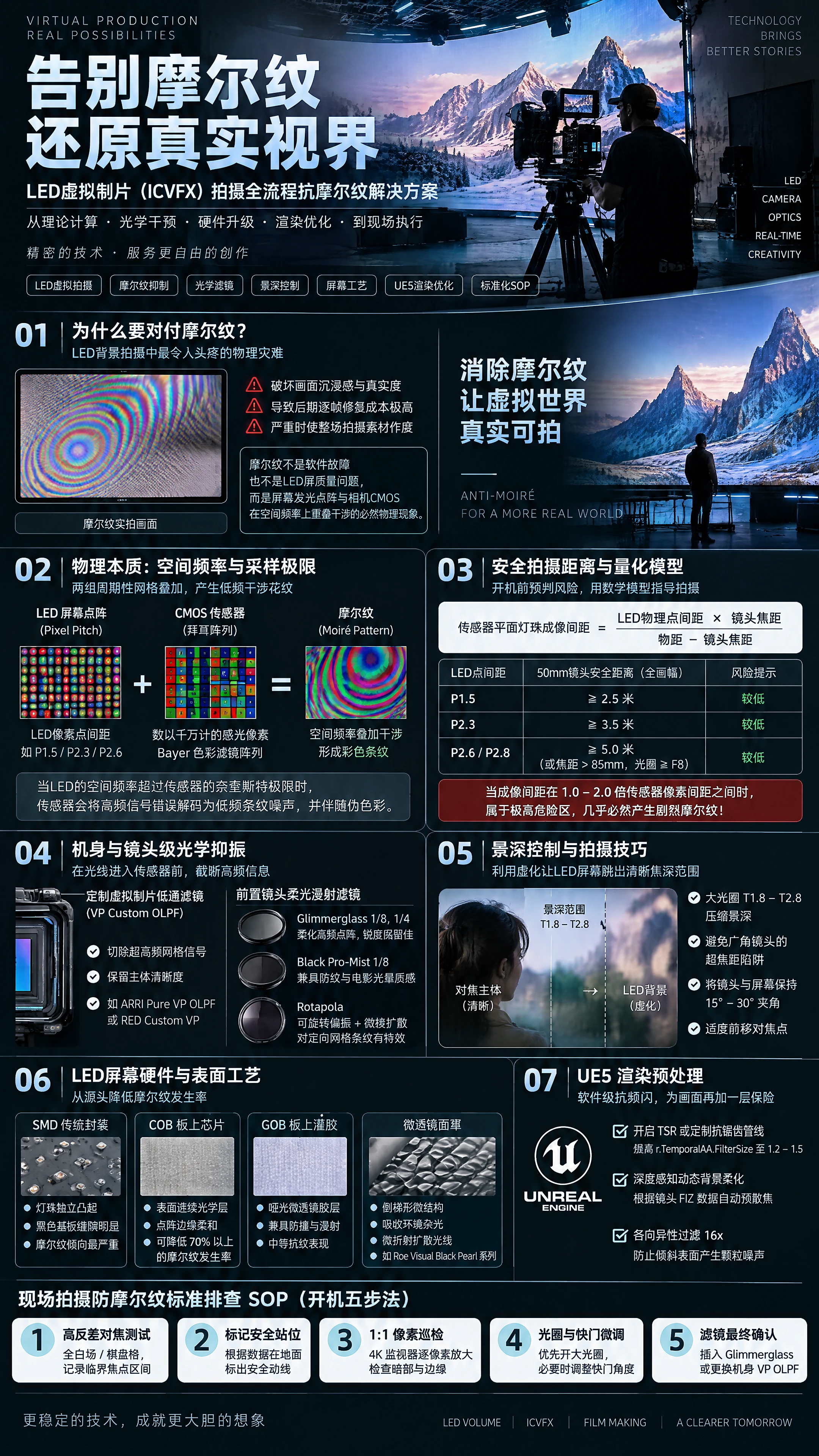
In camera in-camera VFX (ICVFX) shooting based on LED background walls, the most headache-inducing physical disaster for cinematographers and VFX supervisors is none other than the Moiré Pattern. When large-area colored concentric circular stripes, dynamic water ripple patterns, or dense grid flickering appear on the on-set monitor, it not only instantly destroys the immersion and realism of the image, but also leads to extremely costly frame-by-frame repair in post-production compositing, and may even render the entire shoot's footage unusable.
Moiré is not caused by rendering software glitches or LED screen quality defects, but is an inevitable physical phenomenon produced by the overlapping interference in spatial frequency between the screen's physical light-emitting dot matrix and the camera sensor's (CMOS) microlens array. To thoroughly eliminate or effectively suppress moiré, coordinated efforts must be applied across multiple dimensions including the spatial sampling theorem, optical lens intervention, screen packaging processes, and rendering pre-processing. This article will provide a systematic anti-moiré engineering solution spanning from theoretical calculation to on-set practical operation.
I. The Physical Essence of Moiré: Spatial Frequency and the Nyquist Sampling Limit
Moiré is mathematically a form of spatial aliasing of high-frequency spatial signals.
- Two-Dimensional Grid Interference Mechanism The surface of a digital cinema camera's CMOS sensor is covered with tens of millions of micro-photosensitive pixels and a Bayer Color Filter Array, presenting a highly regular periodic grid arrangement. Meanwhile, an LED virtual background wall consists of individual RGB light-emitting diodes arranged in a two-dimensional array at a fixed pixel pitch (e.g., P1.5, P2.3, P2.6). When the camera lens images the high-density periodic light-emitting array on the LED screen onto the CMOS sensor surface, two sets of periodic grids with slight spatial frequency differences or angular tilt undergo spatial overlay interference, producing secondary interference patterns at frequencies far lower than the original grids at the macroscopic level—this is the colored moiré fringe visible to the naked eye.
- Failure of the Nyquist Limit in Optical Imaging The core principle of digital imaging systems is: the spatial sampling frequency of the sensor must be at least twice the highest spatial frequency of the subject to faithfully reproduce image detail. When the projected size of LED pixels on the sensor imaging plane approaches or falls below twice the sensor's physical pixel size, the spatial frequency of the LED light-emitting dot matrix exceeds the Nyquist limit that the sensor can safely sample. The sensor not only fails to resolve individual LED lamps but erroneously decodes their high-frequency energy as low-frequency fringe noise, accompanied by strong false color.
II. Safe Shooting Distance and Optical Parameter Quantification Mathematical Model
To predict moiré risk before rolling, the camera team must establish a quantitative assessment model based on pixel pitch, focal length, focus distance, and sensor size.
- Spatial Projection Magnification and Critical Pixel Pitch Calculation The physical size of the LED pixel pitch projected onto the sensor depends on the photographic magnification. The formula is: Sensor-plane lamp imaging pitch = LED physical pixel pitch × lens focal length ÷ (object distance − lens focal length)
When the calculated imaging pitch is greater than 2.5 times the sensor pixel pitch, moiré risk is low; when the imaging pitch falls between 1.0 and 2.0 times, it is an extremely high-risk zone where severe moiré is almost inevitable; when the imaging pitch is far less than 0.5 times (i.e., extreme telephoto or screen extremely far away), the lamp clusters optically merge completely into a continuous surface light source, and moiré disappears.
- Physical Pixel Pitch and Safe Viewing Distance Rule of Thumb Under standard full-frame cinema camera shooting conditions in the film industry (e.g., ARRI Alexa Mini LF, pixel size approximately 8.25 microns): With a P1.5mm LED screen, using a 50mm lens with the subject focused at a distance of more than 2.5 meters from the screen, the background can achieve smooth filtering. With a P2.3mm screen, the safe distance from subject to screen typically needs to be extended to more than 3.5 meters. With P2.6 or P2.8mm conventional studio screens, if the lens focal length exceeds 85mm or the aperture is stopped down to F8 or above, the safe distance must reach more than 5 meters; otherwise, optical defocus or physical filter methods must be relied upon.
III. Camera Body and Lens-Level Optical Suppression: Custom OLPF and Diffusion Filters
The most efficient and purest means of eliminating moiré at the source is to truncate high-frequency spatial information exceeding the Nyquist limit through physical optical devices before light reaches the CMOS sensor's photosensitive layer.
- Custom Virtual Production Low-Pass Filter (VP Custom OLPF) The built-in IR cut filter and standard OLPF of traditional digital cinema cameras are designed for shooting continuous objects in nature, with relatively lenient spatial cutoff frequencies to preserve ultimate sharpness. In professional LED virtual studios, the mainstream approach is to replace the camera's internal factory OLPF with a virtual production low-pass filter customized for a specific pixel pitch (such as ARRI Pure VP OLPF or RED Custom VP Filter). This filter uses birefringent crystal micro-prisms to precisely split a single incident light point into a tiny quadruple circle of confusion, with its optical defocus radius precisely corresponding to the sensor pixel pitch, physically cutting off ultra-high-frequency grid signals, achieving: actors' eyelashes, hair strands, and prop edges remain razor-sharp as before, while the high-frequency dot matrix of the background LED screen is thoroughly smoothed out, cutting off the breeding ground of moiré from the physical foundation.
- Front Lens Soft Diffusion Filter Selection Strategy If the camera body does not support quick replacement of the internal OLPF, installing a specific optical diffusion filter in the front lens thread or matte box is a highly cost-effective on-set alternative: First recommendation: Glimmerglass series (e.g., 1/8 or 1/4 strength). This filter softens ultra-high-frequency dot matrix while excellently preserving the sharpness of mid-to-low-frequency lines, and is unlikely to produce large-area grayish shadows. Second recommendation: Black Pro-Mist filter (1/8 strength). While breaking up the LED high-frequency grid, it imparts a subtle cinematic film halation quality to LED highlight areas, but attention must be paid to controlling contrast loss in shadow areas under high-contrast scenes. Third recommendation: Rotapola rotatable polarizer and micro-prism diffusion composite filter. By slightly adjusting the light incidence angle, it disrupts the coplanar phase relationship of the two grids, with special effectiveness against directional grid fringes.
IV. Depth of Field Control and Safe Focus Separation Engineering
Using large format and shallow depth of field to achieve physical background blur is the most commonly used composition and anti-moiré technique in virtual production.
- Depth of Field Attenuation and Circle of Confusion (CoC) Control Moiré only occurs in the optical region where the LED screen is in sharp or slightly defocused state. The core logic of on-set setup is to maintain sufficient physical depth separation between the actor (focus point) and the LED screen (background). Set the lens aperture in the T1.8 to T2.8 large aperture range so that the LED screen falls completely outside the lens depth of focus. When the circle of confusion diameter of LED lamps on the screen exceeds 1.5 times the physical center-to-center distance of adjacent lamps, adjacent pixel light spots optically overlap and merge, and the high-frequency grid naturally disintegrates.
- Hyperfocal Trap and Countermeasures with Wide-Angle Panoramic Lenses When shooting wide-angle deep depth of field shots (e.g., 18mm to 24mm), due to the extremely large depth of field of short focal length lenses, the LED screen is often within the sharp focus range regardless, and defocus cannot be relied upon to prevent moiré. Countermeasures: First, tilt the shooting axis. Avoid the lens optical axis being perpendicular at 90 degrees to the LED screen normal; maintain a 15 to 30 degree angle between the camera and the screen to disrupt the vertical coplanar interference period. Second, moderately fine-tune the focus point forward. Lock focus on the actor's chest or the tip of the nose, so that the rear edge of depth of field is cut off just before reaching the LED screen, squeezing out the last centimeter of safety tolerance.
V. Optical Improvement of LED Screen Hardware Structure and Surface Craftsmanship
In addition to camera-side intervention, the physical optical packaging technology of the LED panel itself has a decisive impact on moiré.
- Optical Differences Between SMD, COB, and GOB Packaging Traditional SMD (Surface Mount Device) lamps protrude individually on the PCB, with obvious black recessed substrate gaps between lamps; the light-emitting points present a discrete dot matrix pattern, with the most severe moiré tendency. COB (Chip on Board) technology directly cures micron-level light-emitting chips onto the substrate, with the surface covered by an integrated epoxy resin or silicone continuous optical layer; individual pixel emission exhibits surface-source diffusion characteristics with extremely soft dot matrix edges, reducing moiré occurrence by over 70%. GOB (Glue on Board) adds a matte micro-lens optical adhesive layer on the SMD surface, combining impact protection and optical diffusion effects, representing moderate anti-moiré performance.
- Surface Matte Micro-lens Mask High-end virtual production dedicated LED panels (such as the Roe Visual Black Pearl series) feature a special inverted trapezoidal micro-structure matte mask on the cabinet surface. This mask not only absorbs excess ambient reflected stray light in the studio, but its micro-lens edges also physically refract and diffuse the lamp light at specific angles at the microscopic level, integrating discrete point light sources into a continuous light field without sacrificing forward brightness and color gamut.
VI. Software-Level Anti-Flicker Pre-Compensation in Unreal Engine and Rendering Backend
In addition to optical and hardware methods, pre-processing LED textures through algorithms on the UE5 and render server side can provide a solid last line of defense against moiré.
- TSR and Anti-Aliasing Supersampling Optimization Enable TSR (Temporal Super Resolution) in UE5 or activate a customized virtual production anti-aliasing pipeline. Increase r.TemporalAA.FilterSize to 1.2 to 1.5 to apply slight temporal smoothing to the rendered frustum background, preventing high-frequency geometric edges within the virtual scene (such as distant wire mesh, blinds, high-density textures) from undergoing second harmonic aliasing with the LED screen's own grid.
- Depth-based Pre-defocus Introduce camera metadata linkage in UE5's Post-Process Material: Read the FIZ focal length and focus distance data returned in real time from the physical lens, and calculate the relative depth of field difference between the current virtual background object and the real physical camera. When rendering the in-engine frustum image, actively apply high-quality Gaussian or bokeh blur to virtual distant objects far from the focal plane. This soft defocus overlays with the real lens's optical blur, so that what is presented on the LED screen is itself a de-gridded soft texture, eliminating the high-frequency texture component of the rendered image from the source.
- Anisotropic Filtering Fully Enabled Force-lock texture anisotropic filtering to 16x in project settings. For ground surfaces, diagonal roads, and tilted building surfaces in virtual scenes, prevent low-order MIP Map from generating flickering grainy sampling noise.
VII. On-Set Anti-Moiré Standard Troubleshooting SOP (Five-Step Pre-Roll Method)
To ensure zero incidents on high-pressure shooting sets, the camera crew and virtual pipeline team need to execute a standard troubleshooting process before each setup:
- Step One: High-Contrast Focus Limit Test Light the LED screen to a full white field or high-contrast checkerboard test pattern, point the camera at the screen, slowly rock the focus ring from near to far, observe the monitor waveform and peaking focus indicator, and record the critical focus scale range where moiré occurs.
- Step Two: Actor Safe Standing Position Movement Line Marking Based on the critical depth of field data determined in Step One, mark safe standing lines on the studio floor with T-shaped gaffer tape to ensure the actor's performance area always remains within the safe depth of field band, preventing the actor from moving backward and causing the background to enter the sharp zone.
- Step Three: Monitor 1:1 Micro-Pixel Inspection The director and camera assistant are strictly prohibited from judging quality solely by the scaled image on small monitors. A 4K primary monitor must be used to perform 1:1 pixel-to-pixel zoom inspection on shadow areas and high-contrast edges to check for potential subtle colored interference fringes.
- Step Four: Aperture and Shutter Combination Fine-Tuning If the composition requires medium-to-long focal length and distance is limited, prioritize opening the aperture by one stop (e.g., from T4 to T2.8) to compress depth of field; if slight texture remains, fine-tune the shutter angle (from 180 degrees to 172.8 degrees or 144 degrees) to break the spatiotemporal refresh scan phase resonance.
- Step Five: Filter Final Confirmation Intervention When aperture and distance methods are exhausted, immediately insert a 1/8 strength Glimmerglass into the matte box or replace the camera body with a VP-dedicated OLPF to complete the final optical physical elimination.
VIII. Conclusion
Moiré is by no means an insurmountable physical barrier, but a technical variable that can be thoroughly tamed through precision optical engineering, rigorous mathematical calculation, and systematic software-hardware coordination.
From selecting COB soft mask screens and retrofitting customized low-pass filters, to precisely controlling aperture and depth of field on set and linking UE5 depth-based pre-defocus, the modern virtual production industry has built a complete, gap-free anti-moiré defense system. Only by implementing this set of standard operating procedures throughout the entire shooting workflow can the creative constraints on directors and cinematographers be thoroughly liberated, allowing them to capture every highly textured cinematic shot at will within the LED virtual space.

 简体中文
 English